Decision dossierSPDM-D-0001
- Hand check, torsional shear in the Ø10 journal40.9 vs 40.7 MPa
- Mesh refined at the undercut+0.8 % on the peak stress
- Load directionspigot end turns about +X, as one face
- Modal mesh refinedall 6 modes within 0.4 %
Capability · Drawings to verified designs
Your drawings already hold the design: dimensions, tolerances, materials and notes. We turn them into a parametric 3D model and a knowledge graph, simulate the part and check every number. Every result is linked back to the feature it depends on.
Talk to us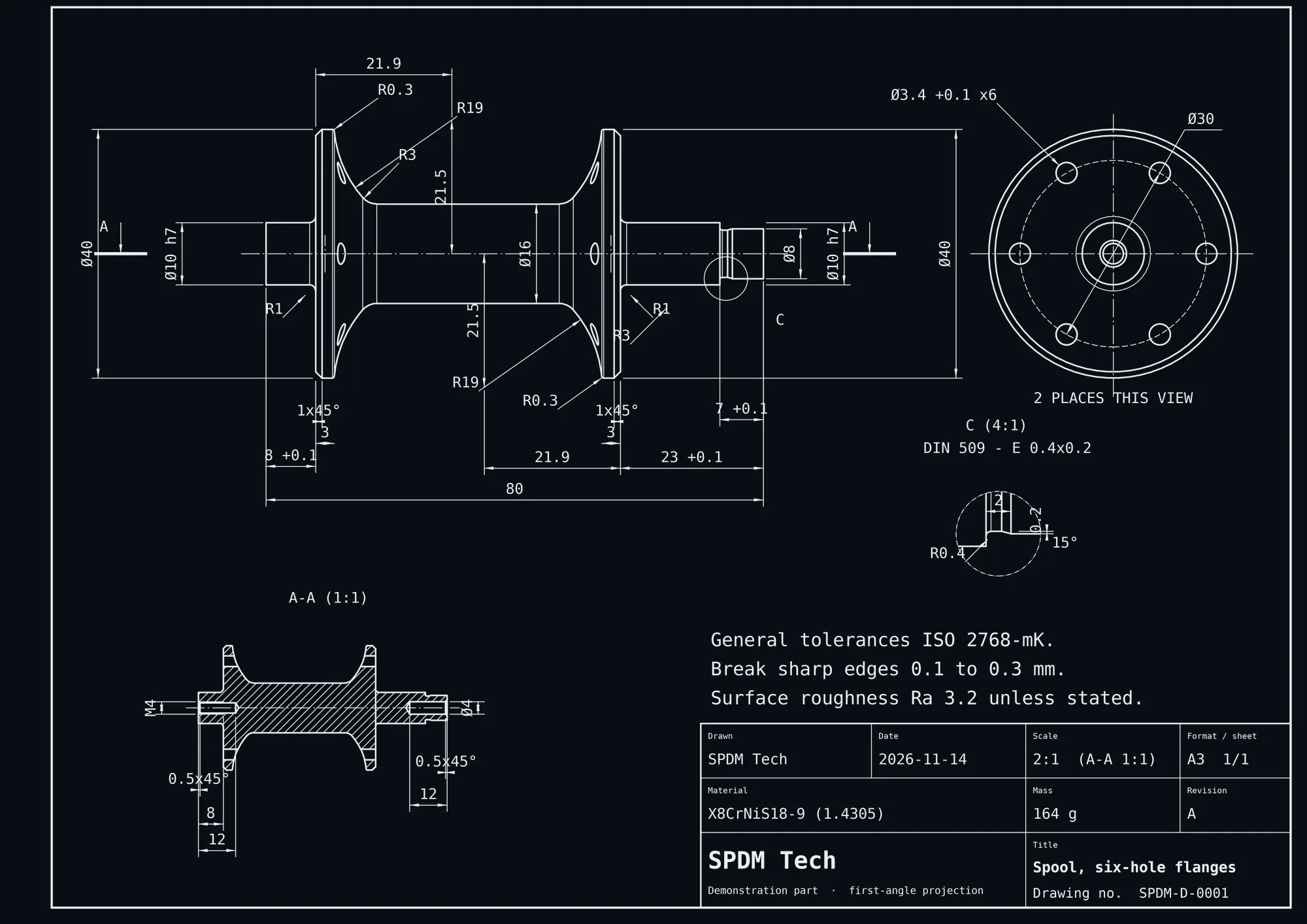
The result
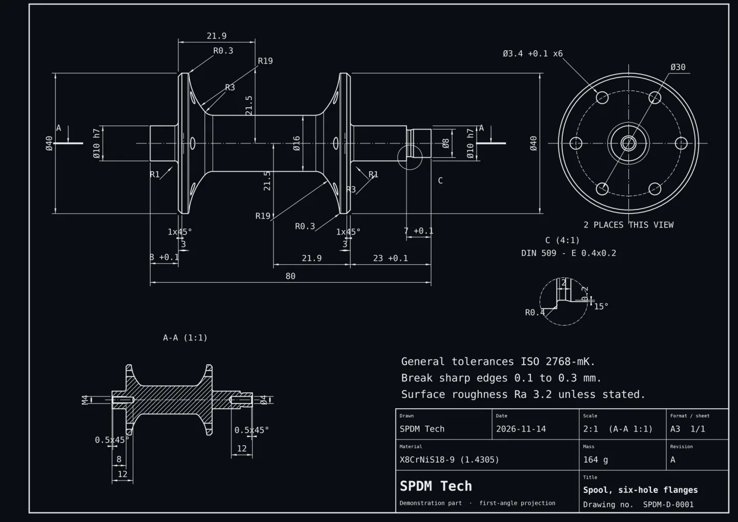
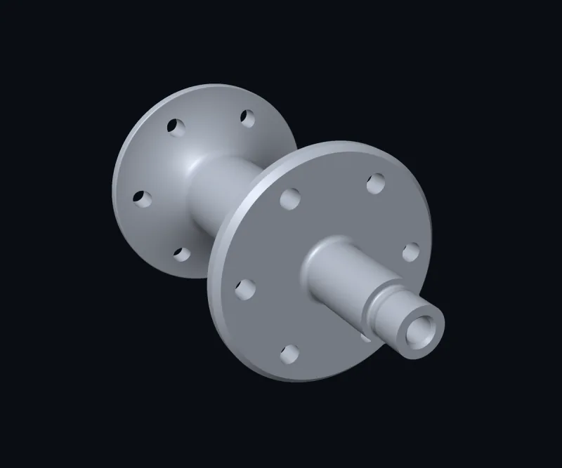
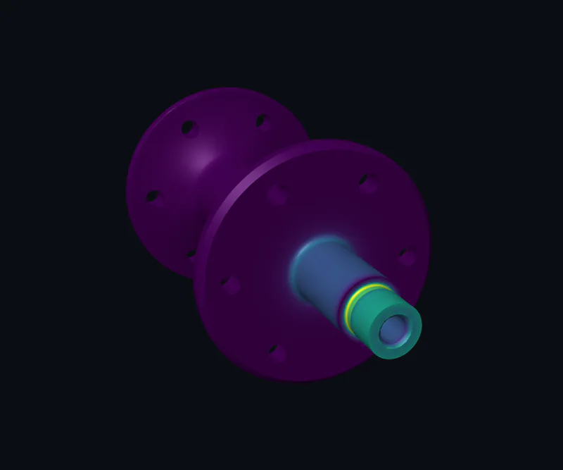
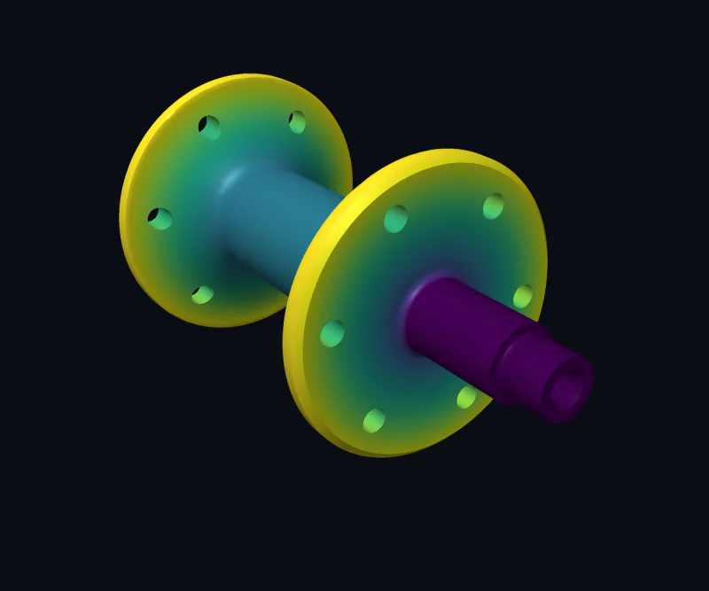
Select a node in the graph and the view follows: a dimension shows the drawing, an analysis its result. Under With simulation, a feature tells you which analysis to rerun if it changes.
How it works
1 · Read
Views and sections, every dimension, tolerance class, material and note, as a designer reads them.
2 · Model
Every value becomes a named parameter and a node in the knowledge graph. Change one, and model and drawing follow.
3 · Mesh
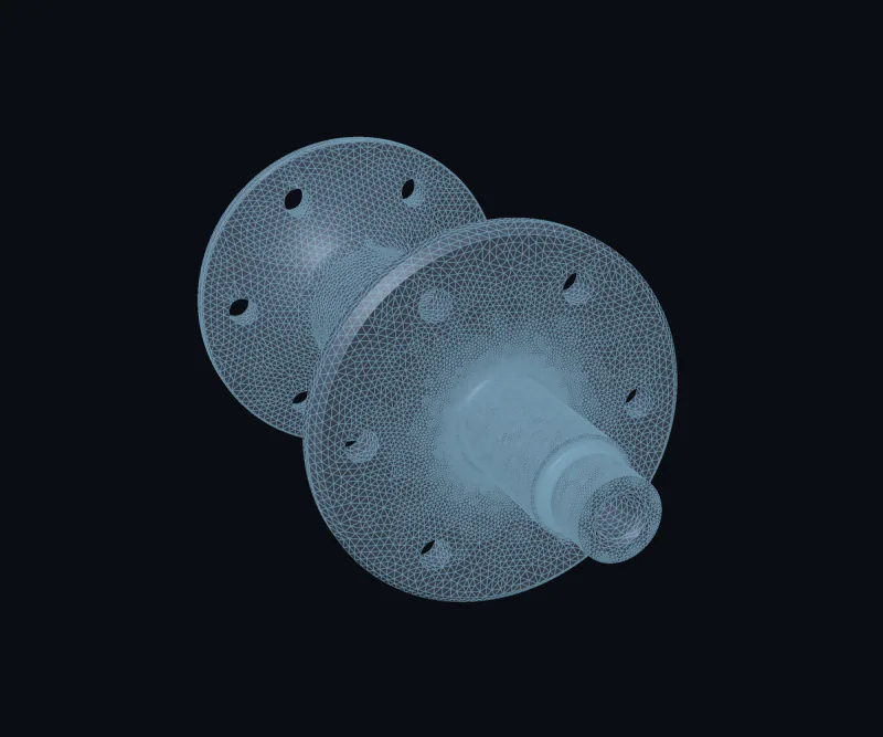
Second-order elements, finest at the undercut where the stress peaks: 0.15 mm.
4 · Solve and check
CalculiX solves both. Every result is checked by hand or by a refined mesh and linked back to its feature.
The evidence
The checks run with every analysis and are reported, not assumed. The strength verdict stays with you: it needs your yield strength and safety factor.
Beyond one part
Proven on real drawings
Dimensions read from two third-party drawings and measured on the models: all match. In the valve housing, a conflict was found: the written 5° contradicts the 10.3° its own dimensions give.
Change with confidence
Because results are linked to features, a design change shows at once which analyses are affected and which answers still hold.
Your archive
Read at scale, released drawings show the rules your designers follow. Those rules can train agents that review new designs before release.
Rules this one drawing already carries
The whole story
Chapters
Assumptions: 8 N·m applied at the spigot end, the hub held fixed, linear elastic stainless steel X8CrNiS18-9 (1.4305). Natural frequencies with the bearing seats supported. SPDM-D-0001 is SPDM Tech's own demonstration part, drawn for this purpose; the third-party drawings named above are not shown.
Pilot partners wanted
SPDM Tech is in its build-up phase. As one of the first pilot partners, you bring one real question, from a circuit board, a drawing or a simulation process, and get a checked answer.