SPDM Tech

Capability · PCB thermal simulation

From Gerber files to a thermal answer.

Send the manufacturing data your board house already has. Get the hot spots, how hot they run and how fast they heat up, each with its check. No CAD model needed.

Talk to us
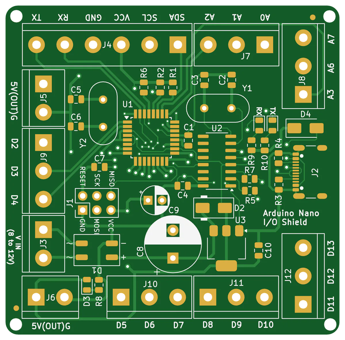
Top side of the circuit board as rendered from its Gerber files
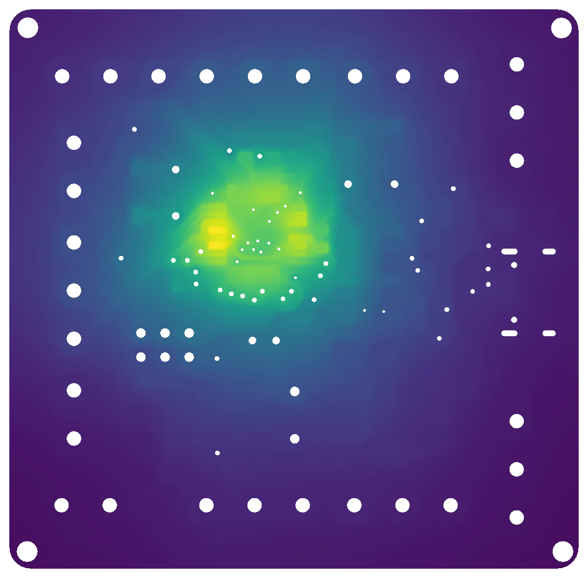
Temperature rise at 1 W, laid over the board layout
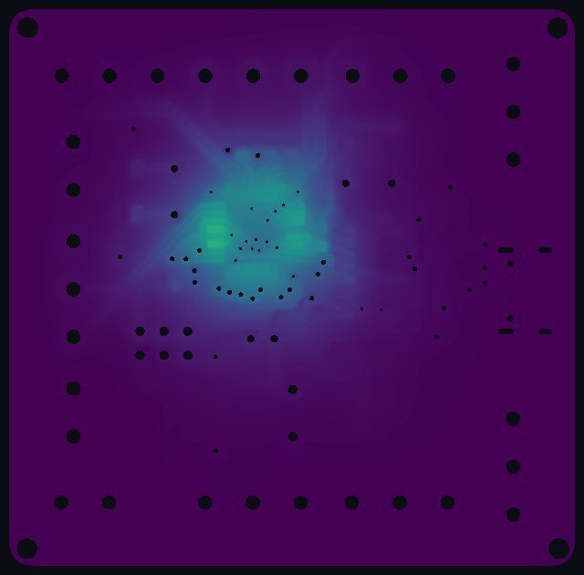
  • +53.6 KHottest pad, 1 W into the microcontroller (U1)
  • 30 sTo reach 63 % of the final temperature
  • 132 sTo reach 90 % of the final temperature
  • 0CAD models built: the geometry comes straight from the Gerber files

The result

Where the heat goes, on the layout you know.

Board layout from the Gerber files Steady-state temperature rise on the top of the board +53.6 K

Drag across the board to compare the layout with the temperature field, or blend the two to see which traces and pads carry the heat.

How it works

Four steps, each one a script you can rerun.

  1. 1 · Input

    Gerber and drill files

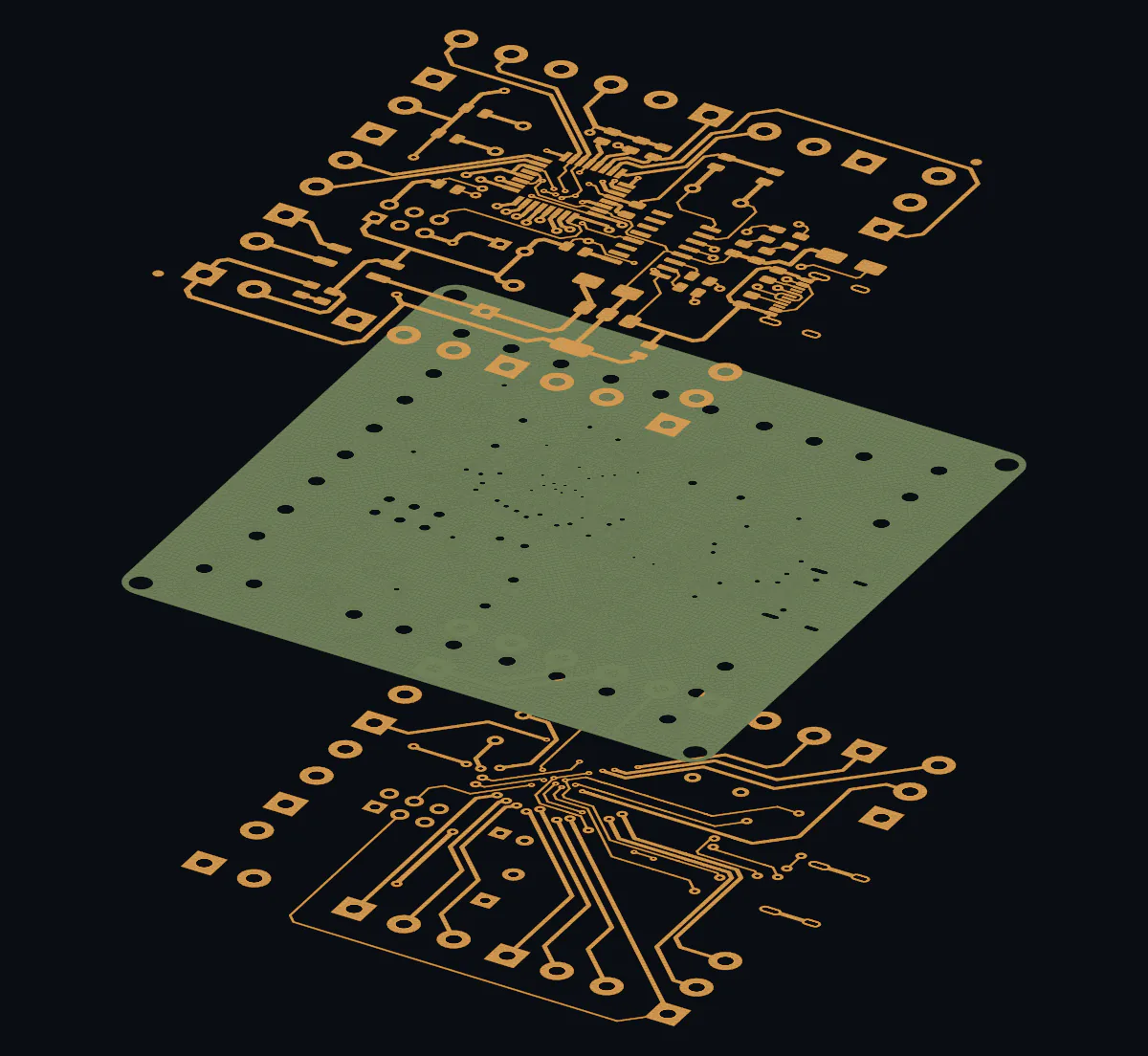
    Exactly as they go to the board house: copper, mask, silkscreen, outline, 93 plated and 6 non-plated holes.

  2. 2 · Model

    Copper, FR-4 and plating

    50 µm copper on each side, a 1.5 mm FR-4 core and 25 µm plating in every hole.

  3. 3 · Mesh

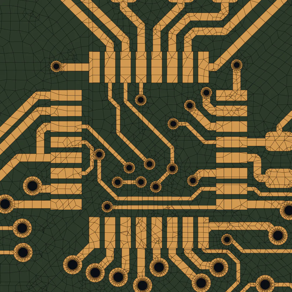
    334,889 nodes

    Layered elements through the board, connected everywhere, finest where the heat enters.

  4. 4 · Solve

    Steady state and heat-up

    CalculiX solves the temperature field: at equilibrium and second by second after power-on.

Over time

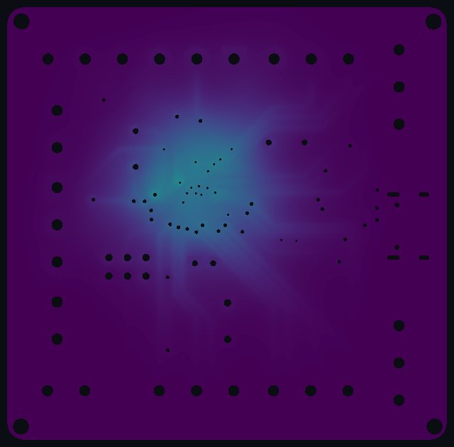
Heating up, from power-on to steady state.

Temperature rise on the top of the board
Top
Temperature rise on the bottom of the board, seen through the board
Bottom, seen through the board

t = 30 s

Top
Bottom

The evidence

Every number comes with its check.

An answer for a design decision has to hold up. These checks run with every analysis and are reported, not assumed.

Decision dossierArduino Nano IO Shield
  • Energy balance1.00005 W of 1 W
  • Hand check, mean surface rise P / hA11.204 vs 11.204 K
  • Mesh refined at U1+1.6 % at the hottest pad
  • Time step halved+0.3 % at 100 s
  • Lumped model, board mean at 100 s6.26 vs 6.34 K

The whole story

From Gerber files to a transient thermal answer, in 77 seconds.

Assumptions: 1 W spread evenly over the 32 pads of U1, the chip itself not modelled. Convection h = 12 W/m²K on the top, bottom and edges. Temperatures are rises above ambient air. The heat-up starts with time steps of 1 ms. Board: Arduino Nano IO Shield, Gerber files from freegerber.com.

Pilot partners wanted

Have a board that runs warm? Send us its Gerber files.

SPDM Tech is in its build-up phase. As one of the first pilot partners, you bring one real question, from a circuit board, a drawing or a simulation process, and get a checked answer.

Become a pilot partner