

Chapter 1
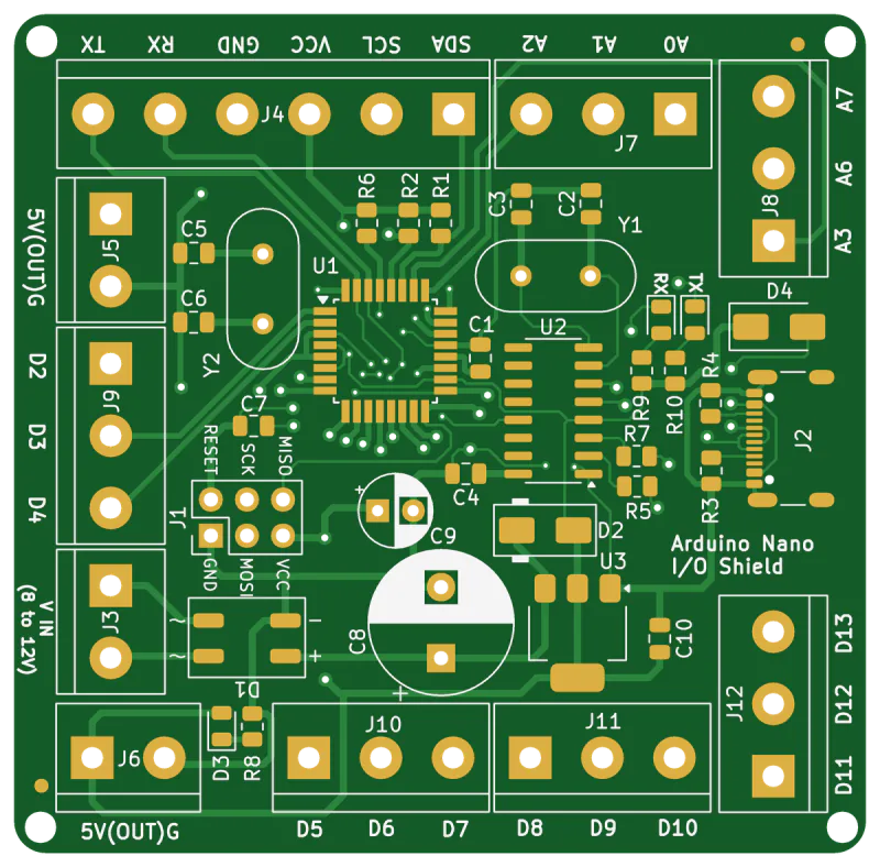
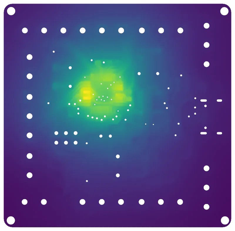
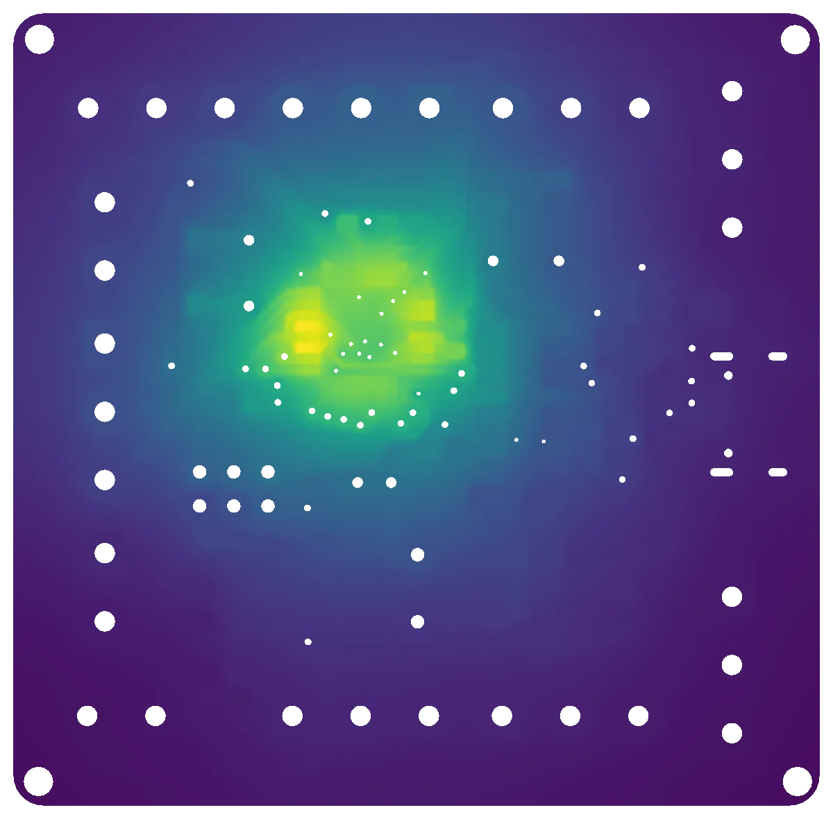
Where does my board run hot, and why?
Hot spots at steady state and during heat-up, laid over the layout you know, with the traces and pads that carry the heat.
See the board modelCapability · Electronics thermal
Your board as it is manufactured, turned into a checked thermal model, reduced to milliseconds and combined with the components on it. Answers for the layout review, the load profile and the derating, each with its check.
Talk to us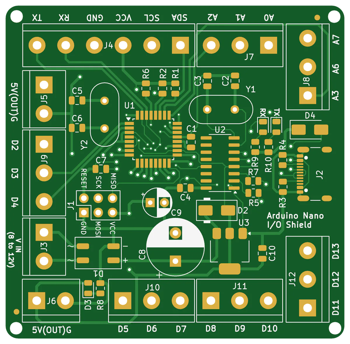
Three chapters
Chapter 1 · Board model
The manufacturing data your board house already has becomes a checked thermal model. No CAD model needed.
+53.6 KHottest pad, 132 s to 90 %
Chapter 2 · Reduced model
The board model condensed to 21 unknowns, with the same answer for any load profile.
334 889 → 21Unknowns, 0.003 K largest difference
Chapter 3 · Coupled components
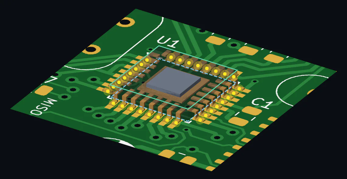
The chip package and the board as reduced models, coupled at their pins. Junction, pins and board in milliseconds.
105.0 K/WJunction to air, 357 unknowns for package and board
Next · not shown yet
More components, heat sinks and the housing as further blocks; the reduced board in the system simulation and in the product itself.
Questions it answers
Chapter 1
Hot spots at steady state and during heat-up, laid over the layout you know, with the traces and pads that carry the heat.
See the board modelChapter 2
Any power over time, without a new simulation: the reduced board answers in milliseconds. Try it on the page.
Try a load profileChapter 3
Junction and pin temperatures for your ambient, your limit and your duty cycle, from the package and the board together.
Check the deratingThe evidence
Each model is checked on its own before the next one builds on it. The details are in each chapter.
Pilot partners wanted
SPDM Tech is in its build-up phase. As one of the first pilot partners, you bring one real question, from a circuit board, a drawing or a simulation process, and get a checked answer.